Pressure Regulator Pid Symbol
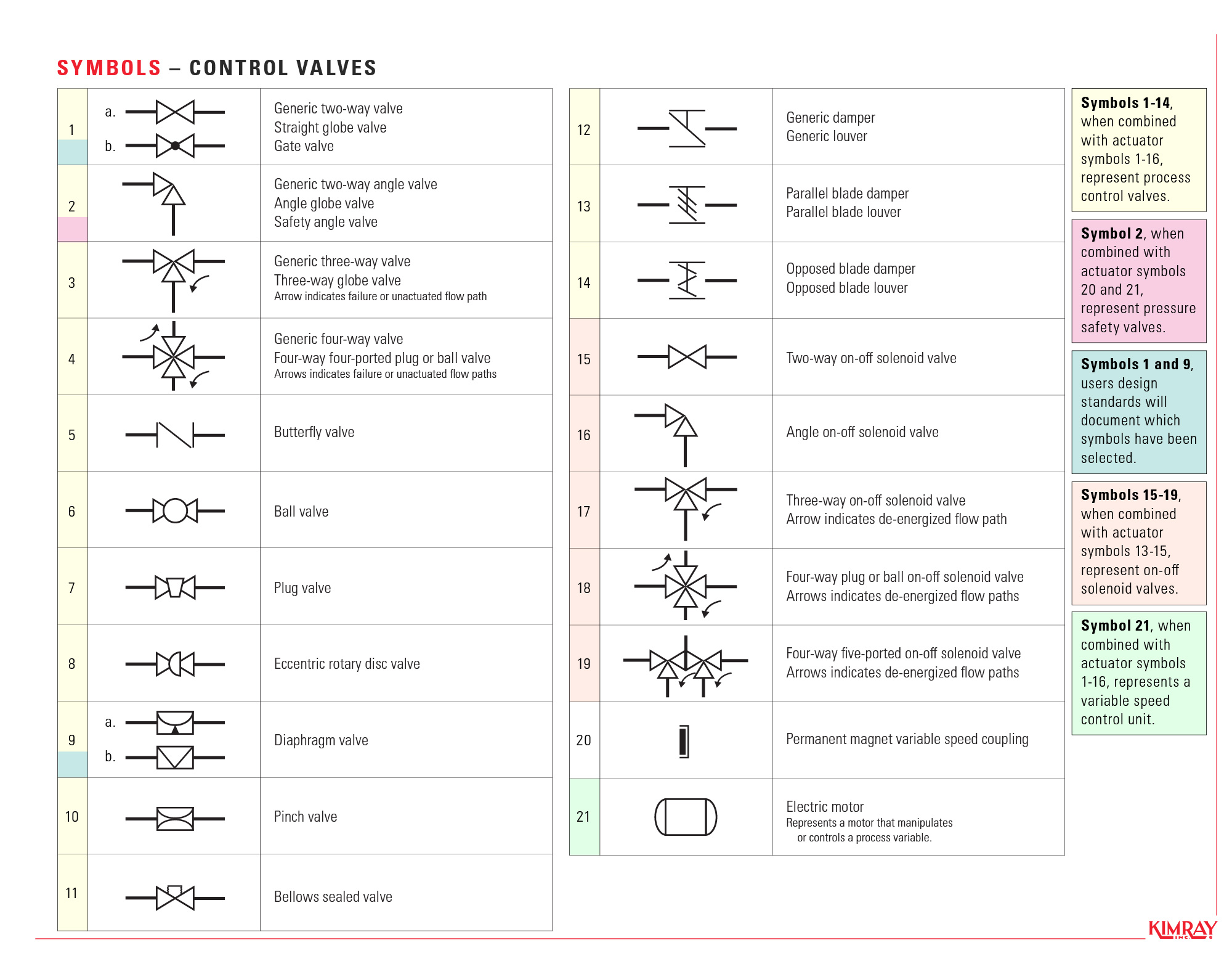
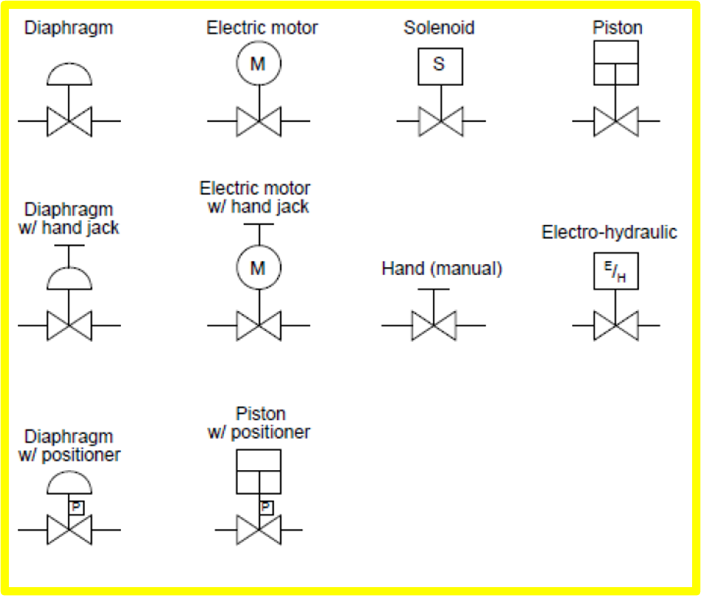
In each process and instrumentation diagram, valves have specific symbols that make them easy to recognize. The symbol typically consists of the actual valve symbol, and the actuation method such as pneumatic, hydraulic, or electric. Table of contents How do I read valve symbols and P&ID diagrams? Valve symbols Valve states Actuator type symbols
Pressure Relief Valve Symbol Basic Hydraulics Hydr 1305 Control
What is a Piping & Instrumentation Diagram (P&ID)? A P&ID is a detailed, visual representation of a process system. P&IDs include standard symbols that explain: Component identification How instruments are connected Where instruments are located The instruments' function within a process

Types of Valves (P&ID symbols) ? REFINERY OIL AND GAS
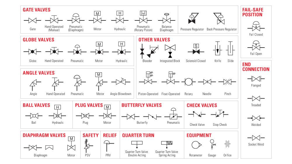
Here is a list of symbols for various types of valves used in process industry. Angle Blowdown Valve Angle Globe Valve Angle Valve Angle Valve Hand Operated Auto Circulation Valve Back Pressure Regulator Balanced Diaphragm Gate Valve Ball Valve Ball Valve Normally Closed Bleeder Valve Butterfly Valve Check Valve 01 Check Valve 02 Control Valve
Pressure relief valve symbol icon Royalty Free Vector Image
Fluid Power Symbols FLUID POWER GRAPHIC SYMBOLS ANSI Y32.10 GRAPHIC SYMBOLS 1. Introduction 1.1 General. either end of symbol. 7.5 Pressure Compensated 7.6 Electrical 7.6.1 Solenoid (Single Winding) 7.6.2 Reversing Motor 7.7 Pilot Pressure 7.7.1 Remote Supply Page 8 of 24
Pressure Relief Valves An Exploration of Industrial Technology
December 21, 2017. A piping and instrumentation diagram (P&ID) is a graphic representation of a process system that includes the piping, vessels, control valves, instrumentation, and other process components and equipment in the system. The P&ID is the primary schematic drawing used for laying out a process control system's installation.
Hydraulic symbology 203 pressure valves
The Schematic Symbol of a Pressure Relief Valve: Explained A pressure relief valve is an essential component in many systems, and its schematic symbol is crucial for understanding how it functions. The symbol consists of several elements that represent the valve's key features and functionality.
Valve Symbols
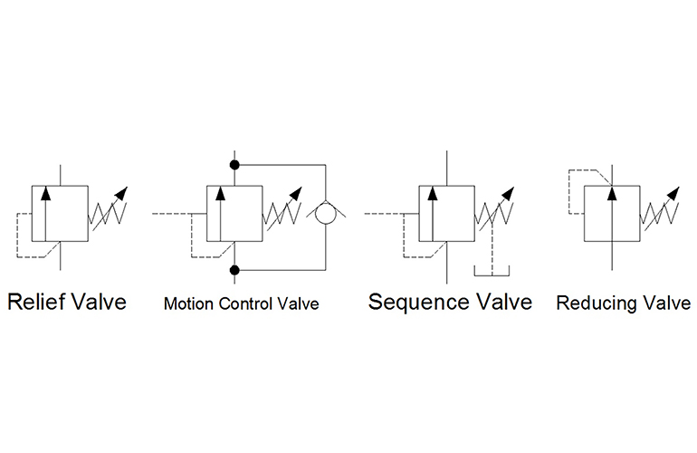
In Hydraulic Symbology 101 ( read it here first ), I covered the basic square used for pressure valves and also showed the most stripped-down versions of the two most commonly used pressure valve symbols, the relief valve and the pressure reducing valve.

Industrial Valve and Actuator Symbols Process Control Solutions Blog
WHAT IS P&ID? P&ID is the acronym for "Piping and instrumentation diagram", i.e. a very detailed diagram showing the processes happening within a plant, the involved equipment, and their interconnections. A set of standardized P&ID symbols is used by process engineers to draft such diagrams.

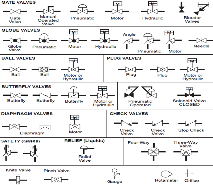
Types Of Valves, Their Functions And Symbols Engineering Discoveries
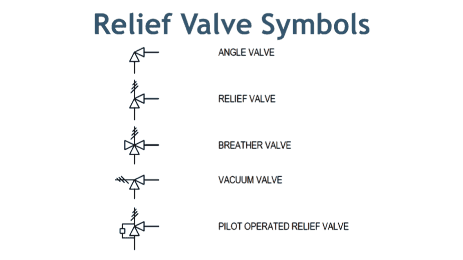
P&ID Quiz - Test yourself, Take This Quiz Relief Valve Symbols Here in the image above, the first symbol is of angle valve. In most cases, a globe valve is used as an angle valve. The next symbol is the relief valve used to protect the piping system or equipment from overpressure. Now the breather valve is used on the cone roof tank.
Control valve symbols in P&id Valves Industrial Automation, PLC
The top symbol indicates a simple, direct operated pressure relief valve. Note how the pilot pressure (shown by the dashed line) comes from the supply line, upstream of the valve. This indicates that as the pressure before the valve increases, it pushes the arrow against the spring and relieves the pressure in the direction of the arrow.
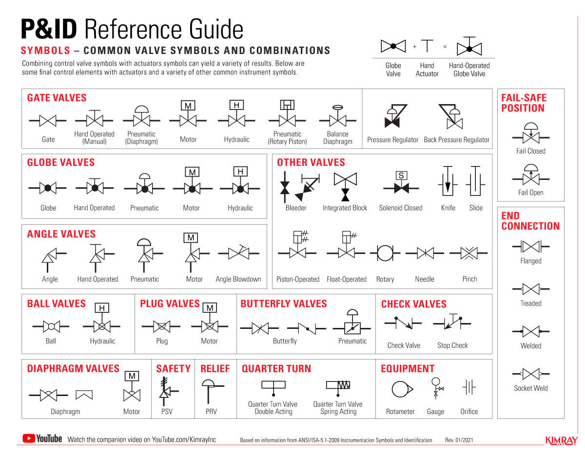
The Most Common Control Valve Symbols on a P&ID Kimray
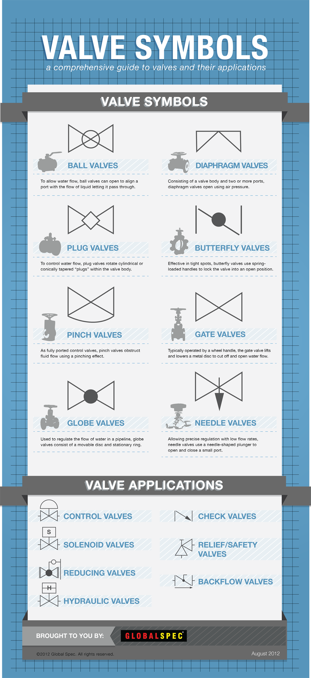
Valve Symbols Valves are used to control the direction, flow rate, and pressure of fluids. Figure 1 shows the symbols that depict the major valve types. It should be noted that globe and gate valves will often be depicted by the same valve symbol. In such cases, information concerning the valve type may be conveyed by the component

How To Interpret Pressure Valves YouTube
Types of valves with P&ID symbols. A valve is an element in a piping system that regulates the flow. A rotary valve turns only at 90°. Linear valves operate when the stem is vertical, and the packing box is above. Self-actuated valves keep set-point pressure in pipelines within predetermined ranges.
Valve Sign Symbols The Engineering Concepts
A Ball valve uses a hollow, rotating ball with a hole going through the ball. The hole lines up with the inlet/outlet when it is open. And the solid sides of the ball line up with the inlet/outlet when the valve is closed. This type of valve symbol looks similar to the globe valve. The ball valve symbol has a larger circle indicating the ball.

Symbols for Valves, Pumps and Electrical Equipment on Ship Marine World
valve is a mechanical device that controls the flow of fluid and pressure within a system or process. valve controls system or process fluid flow and pressure by performing any of the following functions: Stopping and starting fluid flow Varying (throttling) the amount of fluid flow Controlling the direction of fluid flow
Pressure Regulator Pid Symbol
A pressure relief valve is a NC (normally closed) type safety valve which operates when system pressure increases above a maximum working pressure. The normally closed position is indicated by the arrow away from the center line. The dashed line indicates that the system pressure acts against spring force for valve actuation.

Valve Symbols in P&ID Ball Valve, Relief Valve and more
Piping and Instrument Diagram Standard Symbols Detailed Documentation provides a standard set of shapes & symbols for documenting P&ID and PFD, including standard shapes of instrument, valves, pump, heating exchanges, mixers, crushers, vessels, compressors, filters, motors and connecting shapes. Or Gate Not Gate Correcting Element Diamond